
Standard Non-Condensing
Component Name
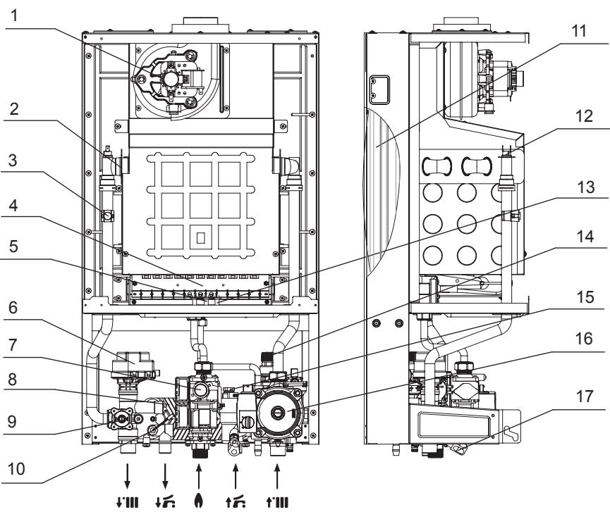
1.Combustion Fan
2.Primary Heat Exchanger
3.Heating Temperature Sensor (NTC)
4.Burner
5.Ignition Electrode
6.Three-way Valve Motor
7.Gas Proportional Valve
8.Plate Heat Exchanger
9.Water Pressure Switch
10.DHW Temperature Sensor (NTC)
11.Expansion Vessel
12.Overheat Protection Thermostat
13.Flame Detection Electrode
14.Safety Relief Valve
15.Water Flow Sensor
16.Circulation Pump
17.Filling Valve
Gas Inlet (G3/4”)
Hot Water Outlet (G1/2”)
Cold Water Inlet (G1/2”)
Heating Return (G3/4”)
Heating Flow Outlet (G3/4”)
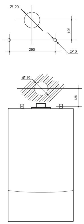
Product Installation and Flue Pipe Drilling
- Please install the flue system strictly according to the instructions
provided for the air intake and exhaust flue installation. - For the heating system, use copper pipes, heat-resistant aluminum-plastic pipes, or dedicated heat-resistant and pressure-resistant plastic pipes.
- This product is installed via the air intake and exhaust flue system using the (1P type) balanced flue configuration.
- To facilitate installation and maintenance, appropriate shut-off ball valves should be installed at all connection points.
- The wall used for mounting the product must be able to bear a load of more than 60 kg.
- If the wall insulation layer is relatively thick, please consider using extended metal expansion bolts.
- Ensure that the wall-hung boiler is securely fixed to the wall. Installing anti-vibration pads where appropriate can further reduce operating noise.
- Valves for each room are preferably installed on the return water manifold.
- To prevent freezing damage, please keep all room valves open during long periods of absence.
Cold Water Inlet Pipe Installation
- The diameter of the cold water inlet connection of this product is 1/2″.
- A shut-off ball valve must be installed at the water inlet.
- To ensure normal operation, the inlet water pressure must be no less than 0.1 MPa. Before connecting the inlet pipe to the product, open the inlet shut-off valve to flush out sand, debris, and other residues inside the pipeline.After completing the pressure test, close the inlet valve, remove the inlet water filter, clean it thoroughly, and reinstall it.
- If the inlet water pressure is too low, a booster pump should be installed.
Domestic Hot Water Pipe Installation
- Domestic Hot Water Pipe InstallationThe diameter of the domestic hot water outlet connection of this product is 1/2″.
- The length of the hot water pipeline should be kept as short as possible to minimize heat loss.
- During installation, ensure that all connections are properly sealed and free from leakage.
- All cold water and hot water pipelines must be fully insulated.Complex piping layouts should be avoided as much as possible, and the use of excessive fittings or connectors should be minimized.
Heating Pipe Installation
- When installing the heating pipeline, it is recommended to use a manifold, and the length of each branch pipe should be kept as consistent as possible.
- The heating pipe connection diameter of this product is 3/4″.
- The branch pipes of the manifold should be connected downwards.
The manifold must be insulated before connecting it to the pipelines of each room.
(For branch pipes leading to each room, Ø9–15 mm pipes should be used.) - When using underfloor heating, the heating pipes must be buried underground without any joints. Any leakage will make maintenance and repair difficult.
- The diameters of the heating supply and return pipes should be kept consistent.
The length of intermediate pipelines should be minimized to reduce heat loss.
If there is a significant difference in the area of heated rooms, additional piping should be installed in
larger rooms to ensure uniform temperature distribution. - All exposed pipes must be wrapped with insulation material with a thickness of at least 25 mm to prevent freezing.
(In extremely cold regions, the insulation thickness should exceed 50 mm.) - The maximum operating water temperature of the system is 85°C.
Product Installation
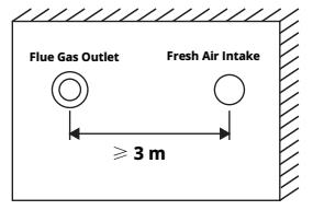
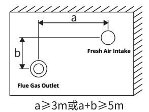
- When set on the same wall in the same direction and at the same horizontal height, the horizontal distance between the walls should not be less than 3m.
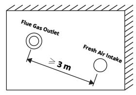
- The two are not at the same horizontal height, and the air supply and exhaust ports should be arranged as much as possible above the fresh air intake. When the air supply and exhaust ports are above, the straight-line distance between them should not be less than 3m.
- When the two are not at the same horizontal height and the exhaust port is below, the horizontal distance a between the walls should not be less than 3m, or the sum of the horizontal distance a and the vertical distance b between the walls should not be less than 5m.
- The distance between the exhaust port and the fresh air outlet must comply with local standards or regulations.
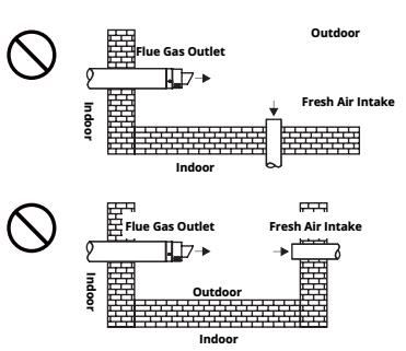
The following situations do not allow installation.
- The distance between the exhaust port and the new air outlet must ensure that the discharged smoke does not enter the room, and the position of the exhaust port and the new air outlet should be as far away as possible.
- The distance between the exhaust port and the fresh air outlet also needs to meet the positional relationship between households and buildings.
- During installation, it is necessary to check the position of the new air outlet around the exhaust port.
Connection of control device
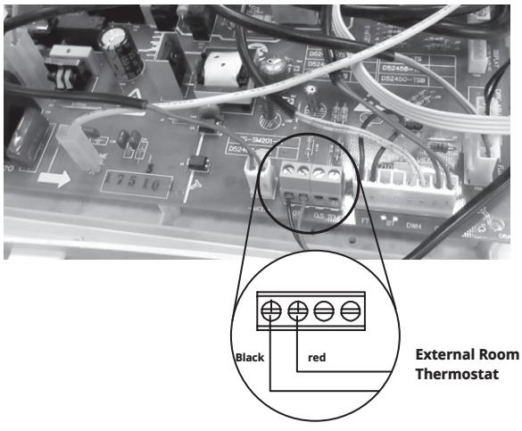
This product can be equipped with an indoor temperature controller, which is used to control and display the temperature of the heated room.
- Loosen the terminal screws of the short circuit and remove the short circuit;
- Connect the two wires of the room temperature controller to the terminal posts respectively.
Warning!
The two wires that input the controller can only be switch signals and cannot have any external voltage or current signals, otherwise it may damage the controller.
Gas flow rate and gas type adjustment parameter table
| Gas type | Natural gas (12T) | ||||
|---|---|---|---|---|---|
| Rated output power | 18.0 kW | 23.6kW | 28.0 kW | 32.0 kW | 35.6 kW |
| Rated gas supply pressure PGA (mbar) | 20 | 20 | 20 | 20 | 20 |
| Maximum pressure after valve PGBmax (mbar) | 12.0 | 11.5 | 12.8 | 13.0 | 13.0 |
| Minimum value of valve back pressure PGBmin (mbar) | 1.3 | 1.2 | 1.3 | 0.9 | 1.6 |
| Rated power gas consumption (natural gas) m3/h | 2.12 | 2.79 | 3.33 | 3.81 | 4.23 |
| Minimum power gas consumption (natural gas) m3/h | 0.74 | 0.79 | 1.16 | 1.33 | 1.48 |
Note: The pressure behind the valve is a reference value.
Pump characteristic curve diagram
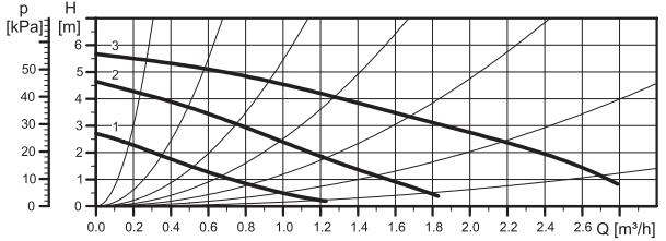
Characteristic curve diagram of 6-meter fixed frequency water pump
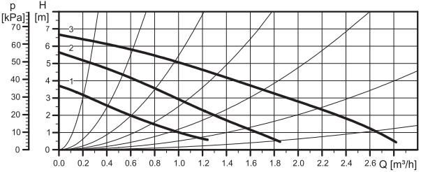
Characteristic curve diagram of 7-meter fixed frequency water pump
Characteristic curve diagram of 5-7 meter variable frequency water pump
Gas flow rate and gas type adjustment parameter table
| Gas type | Natural gas (12T) |
|---|---|
| Rated output power | 44.5 kW |
| Rated gas supply pressure PGA (mbar) | 20 |
| Maximum pressure after valve PGBmax (mbar) | 12.5 |
| Minimum value of valve back pressure PGBmin (mbar) | 2.0 |
| Rated power gas consumption (natural gas) m3/h | 5.29 |
| Minimum power gas consumption (natural gas) m3/h | 2.01 |
Note: The pressure behind the valve is a reference value.
According to the Management Measures for the Restriction of the Use of Hazardous Substances in Electrical and Electronic Products of the People's Republic of China, the following section lists the names and contents of hazardous substances that may be contained in this product.
Important Notice:
This document is intended for reference by qualified installation and service personnel only.
Other individuals may read the contents for information purposes, but must not carry out installation, adjustment, disassembly, or any operation on the equipment.
Unauthorized operation by unqualified personnel may result in safety risks, and the safety of such operations cannot be ensured.