
50kW Commercial
Product Installation and Drilling of Exhaust Pipes
- For the installation of the exhaust pipe, please follow the instructions for the installation of the supply and exhaust ducts.
- For heating pipelines, please use copper pipes, heat-resistant aluminum-plastic pipes, or specialized plastic pipes that are heat-resistant and pressure-resistant.
- The product is installed by connecting the exhaust pipe according to the (1P-type) exhaust method.
- For easy installation and maintenance, please install corresponding switch ball valves at each connection port.
- The wall where this product is mounted must be able to bear a weight of over 60kg.
- If the wall insulation layer is relatively thick, consider using extended metal expansion bolts as appropriate.
- Ensure the wall-mounted boiler is securely fastened to the wall. Adding appropriate anti-vibration pads can make it operate more quietly.
- Valves for each room are preferably installed on the return water manifold.
- To prevent freezing damage, please keep all room valves open during long periods of absence.
Install the exhaust pipe
- The wall mounted boilers manufactured and sold by our company must use our company’s dedicated exhaust pipe. If the product is damaged or accidents occur due to the failure to use specialized components (including exhaust pipes), our company shall not be responsible.
- The length of the exhaust pipe is 1 meter and 1 bend.
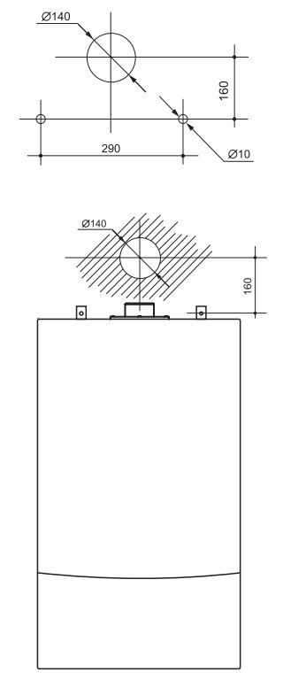
Determine the position of the exhaust pipe outlet
- The exhaust pipe should be installed on a wall that leads to the outside, and the position of the smoke exhaust outlet must have unobstructed air flow.
- The exhaust outlet should be installed in a location with less personnel access, less likely to be exposed to rain, snow, and strong winds. Do not place dangerous goods or obstacles around.
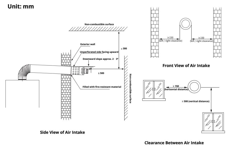
- The exterior of the exhaust pipe should be inclined downwards by about 2-3 degrees to prevent rain and snow from flowing into the wall mounted boiler, and it should be fixed properly.
- There should be no gap for exhaust gas to enter the indoor space at the connection point of the exhaust pipe hole to the outdoor wall, and it should be filled with flame-retardant materials. The suction hole should be at least 20mm away from the wall, and there should be no leakage at the connection part.
- The exhaust pipe must lead to the outdoors, with a minimum distance of 5 meters or more from the air conditioner and ventilation fan, and not on the same wall. The distance between the exhaust port and the air conditioning and ventilation fan must comply with local standards or regulations.
Product Installation
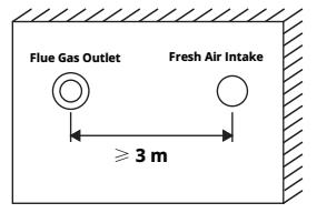
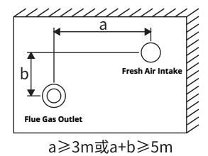
- When set on the same wall in the same direction and at the same horizontal height, the horizontal distance between the walls should not be less than 3m.
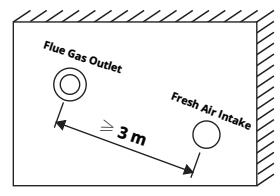
- The two are not at the same horizontal height, and the air supply and exhaust ports should be arranged as much as possible above the fresh air intake. When the air supply and exhaust ports are above, the straight-line distance between them should not be less than 3m.
- When the two are not at the same horizontal height and the exhaust port is below, the horizontal distance a between the walls should not be less than 3m, or the sum of the horizontal distance a and the vertical distance b between the walls should not be less than 5m.
- The distance between the exhaust port and the fresh air outlet must comply with local standards or regulations.
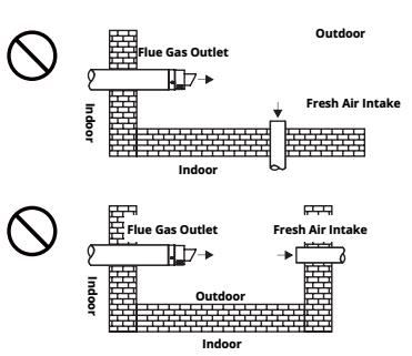
The following situations do not allow installation.
- The distance between the exhaust port and the new air outlet must ensure that the discharged smoke does not enter the room, and the position of the exhaust port and the new air outlet should be as far away as possible.
- The distance between the exhaust port and the fresh air outlet also needs to meet the positional relationship between households and buildings.
- During installation, it is necessary to check the position of the new air outlet around the exhaust port.
Pump characteristic curve diagram
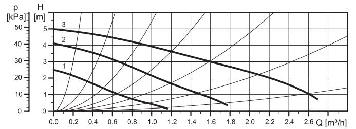
Characteristic curve diagram of 5-meter fixed frequency water pump
Characteristic curve diagram of 6-meter fixed frequency water pump
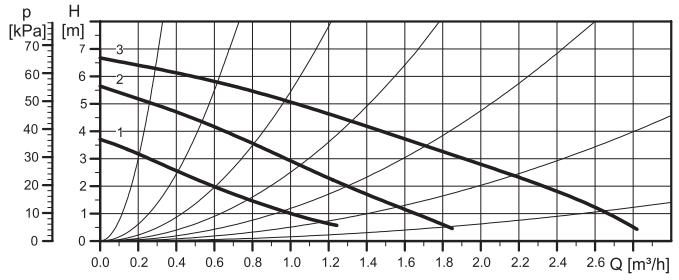
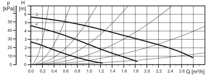
Characteristic curve diagram of 7-meter fixed frequency water pump
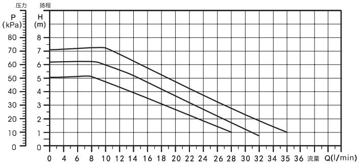
Characteristic curve diagram of 5-7-meter fixed frequency water pump
Important Notice:
This document is intended for reference by qualified installation and service personnel only.
Other individuals may read the contents for information purposes, but must not carry out installation, adjustment, disassembly, or any operation on the equipment.
Unauthorized operation by unqualified personnel may result in safety risks, and the safety of such operations cannot be ensured.