
Condensing Models
Product Installation
- This wall-mounted boiler must be installed by qualified installers.
- Please install and use the equipment in accordance with the national standard GB 25034-2020 “Gas-fired Heating Water Heaters” and the standard T/CECS215-2017 “Technical Regulations for the Application of Gas-fired Heating Water Heaters”, as well as other relevant regulations and provisions.
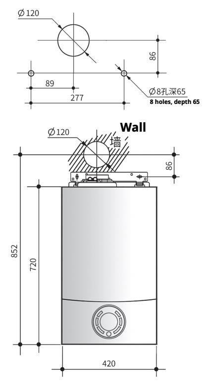
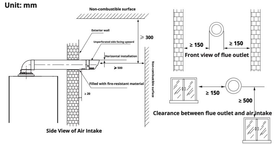
- For correct installation, please drill holes according to the marked dimensions.
- Incorrect installation of the exhaust pipe may affect the normal operation of the wall-mounted boiler and compromise its safety in use.
- Before initial use, please thoroughly clean all heating water pipelines. In areas with hard water (calcium and magnesium compounds greater than 450mg/L), users are advised to use a dedicated scale reducer. The company will not be responsible for any malfunctions of the wall-mounted boiler that may be caused by residual substances in the heating pipeline or sediment generated from using groundwater as heating water.
- Adding antifreeze to the heating water pipeline will not only shorten the lifespan of the wall-mounted boiler but also cause malfunctions. Please refrain from injecting antifreeze.
- The total flow rate of the heating system should be ensured to be above 500 liters per hour.
- After installation, the installer should mark the positions of the gas supply and exhaust systems of the wall-mounted boiler. The installer should also explain to the user how to use the wall-mounted boiler and its safety devices. This instruction manual should be handed over to the user for safekeeping and future reference.
Precautions before installation
- Confirm whether the type of gas used at the installation location is consistent with the gas specified on the wall mounted boiler nameplate. Please carefully read the label on the side of the wall mounted boiler.
- The gas connection pipe of this product must use metal pipes or gas pipes designated by the gas management department, and ensure that there is no gas leakage during installation.
- This product is dedicated for 220V~50Hz.
- Please make sure to use the gas type and pressure indicated on the nameplate, and it is strictly prohibited to change the gas type.
Power sockets should comply with relevant national standards and ensure good and effective grounding. - If the power cord is damaged, to avoid danger, it must be replaced by our after-sales service center or authorized repair department.
Gas flow and gas type adjustment parameter table
| Gas type | Natural gas (12T) | |||
|---|---|---|---|---|
| Rated output power | 24.0 kW | 28.0 kW | 31.0 kW | 33.6 kW |
| Rated gas supply pressure PGA (mbar) | 20 | 20 | 20 | 20 |
| CO2 range value (%) at maximum power | 9.2±0.1 | 9.2±0.1 | 9.2±0.1 | 9.2±0.1 |
| CO2 range value at minimum power (%) | 8.8±0.1 | 8.8±0.1 | 8.8±0.1 | 8.8±0.1 |
| Gas flow rate (natural gas) m3/h | 2.6 | 3.0 | 3.4 | 3.7 |
Note: The pressure behind the valve is a reference value.
Selection of installation site
Before selecting an installation site, please be sure to carefully read the following items:
1. Fire prevention requirements
Storage rooms for flammable materials such as gasoline, benzene, and adhesives should not be used as installation sites due to the risk of fire.
- Please confirm that the walls, ceilings, etc. around the installation site are made of flame-retardant materials and have effective fire prevention intervals.
- Please install this machine on a flame-retardant wall (if the wall is combustible, please install a heat shield).
- When the materials on the left and right walls are made of flame-retardant substances, a distance of at least 45mm should be maintained.
- The top of the wall-mounted boiler should be at least 150mm away from flammable materials.
- If the wall surface is combustible, the distance from the left and right sides to the wall-mounted boiler should be at least 150mm.
- When the distance to the combustible wall surface is less than 150mm, heat insulation boards should be installed on both sides. The distance from the heat insulation board to the left and right sides of the wall-mounted boiler should be more than 45mm.
* The heat shield should be made of non-combustible materials such as metal with a thickness of 3mm or more.
2. Precautions before installation
- This product is designed for indoor use only. It is strictly prohibited to install this wall-mounted boiler outdoors.
- It is strictly prohibited to install this wall-mounted boiler in the bathroom.
- Please do not install it in places where corrosive exhaust gases such as ammonia, chlorine, sulfur, and acids are generated. This will accelerate the damage to the wall-mounted boiler and lead to incomplete combustion.
- Avoid installing near the cold or hot air outlets of air conditioners or heaters.
- Please do not install near electrical equipment.
- Please do not install near stairs or emergency exits.
3. Check the necessary space for maintenance
- Please ensure that there is sufficient space for inspection and maintenance.
- There should be a space of at least 600mm in front of this product.
Product installation and drilling of smoke exhaust ducts
- Please follow the instructions for installing exhaust ducts when installing smoke exhaust ducts.
- For heating pipelines, please use copper pipes or heat-resistant aluminum-plastic pipes, or specialized plastic pipes that are both heat-resistant and pressure-resistant.
- The product is installed by connecting the exhaust pipe according to the (1G type) exhaust and supply method.
- For ease of installation and maintenance, please equip each connection port with the corresponding ball valve switch.
- The wall surface where this product is mounted should be able to bear a weight of over 60kg.
- If the insulation layer of the wall is relatively thick, please consider using extended metal expansion bolts as appropriate.
- Please ensure that the wall-mounted boiler is securely installed on the wall, and add shockproof pads as appropriate to reduce noise during operation.
- Valves for each room are preferably installed on the return water manifold.
- To prevent freezing damage, please keep all room valves open during long periods of absence.
Installation of cold water inlet pipe
- The diameter of the cold water inlet pipe connector of this product is 1/2″.
- Please install a stop valve at the water inlet.
- To ensure normal use of this product, the inlet water pressure should be maintained above 0.1 MPa.
- Before connecting the inlet pipe to this product, please open the inlet shut-off valve to allow any residues such as sand and gravel inside the pipe to be completely drained. After conducting a pressure test, close the inlet valve again. Remove the inlet filter, clean it thoroughly, and then reinstall it.
- If the water inlet pressure is too low, please use a booster pump.
Installation of domestic hot water pipeline
- The diameter of the hot water discharge pipe connection of this product is 1/2″.
- The length of the hot water pipe should be minimized to avoid heat loss.
- When connecting, please ensure there is no water leakage.
- Both cold and hot water pipes must be insulated.
- Try to avoid complex piping construction and minimize the use of connectors.
Heating pipeline installation
- When installing heating pipelines, please use distributors as much as possible and try to keep the length of each distribution pipe consistent.
- The heating pipe connectors of this product all have a diameter of 3/4″. The branch pipes of the distributor should be connected downward, and the distributor needs to be insulated before connecting the discharge pipes of each room. (Please use 09-15mm pipes from the branch pipes to each room)
- When using floor heating, the heating pipes should be buried underground without any joints. In case of leakage, it will bring inconvenience to the repair.
- Please standardize the diameters of the hot water supply pipe and the return pipe. Try to shorten the length of the intermediate piping to reduce heat loss.
- If the area of the heating rooms varies greatly, please adopt the method of increasing the number of pipelines in the larger rooms to ensure uniform temperature distribution across all rooms.
- The exposed part of the pipeline must be wrapped with insulation material with a thickness of at least 25mm to prevent the pipeline from freezing. (In particularly cold regions, the thickness should exceed 50mm)
- The maximum operating temperature of the system is 85℃.
Installing exhaust and air supply ducts
- The wall-mounted boilers manufactured and sold by our company must use our company’s dedicated air supply and exhaust flue tubes. We will not be responsible for any product damage or accidents caused by the failure to use dedicated components (including air supply and exhaust flue tubes).
- Pipes that may be affected by heat (such as plastic pipes or pipes with plastic coatings inside) should not be connected to the condensing furnace.
- The exhaust temperature is limited to around 98℃. If the temperature exceeds this limit, the wall-mounted boiler will shut down and trigger an alarm.
- The maximum length of the exhaust pipe is 1 meter with 1 bend.
Determine the position of the exhaust pipe outlet
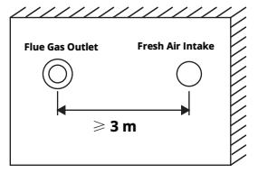
- The exhaust pipe should be installed on a wall that leads to the outside, and the smoke exhaust outlet must be located where air can flow freely.
- The exhaust outlet should be installed in a location where there are few personnel access, it is not prone to rain or snow, and can be sheltered from strong winds. Do not place dangerous goods or obstacles around it.
- The exhaust pipe must be installed horizontally and led outdoors (with the inner tube of the smoke pipe tilted upwards by 3°), and properly fixed.
- The connection between the exhaust pipe hole and the wall leading to the outside should have no gaps that allow exhaust gas to enter the room, and it should be filled with flame-retardant materials. The air intake hole should be at least 20mm away from the wall, and the connecting part should be free of leaks.
- The exhaust pipe must be routed outdoors, with a minimum distance of at least 5 meters from air conditioners and ventilation fans, and must not be located on the same wall. The distance between the exhaust and supply outlets and air conditioners and ventilation fans must comply with local standards or regulations.
Product Installation
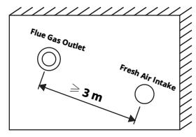
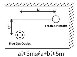
- When set on the same wall in the same direction and at the same horizontal height, the horizontal distance between the walls should not be less than 3m.
- The two are not at the same horizontal height, and the air supply and exhaust ports should be arranged as much as possible above the fresh air intake. When the air supply and exhaust ports are above, the straight-line distance between them should not be less than 3m.
- When the two are not at the same horizontal height and the exhaust port is below, the horizontal distance a between the walls should not be less than 3m, or the sum of the horizontal distance a and the vertical distance b between the walls should not be less than 5m.
- The distance between the exhaust port and the fresh air outlet must comply with local standards or regulations.
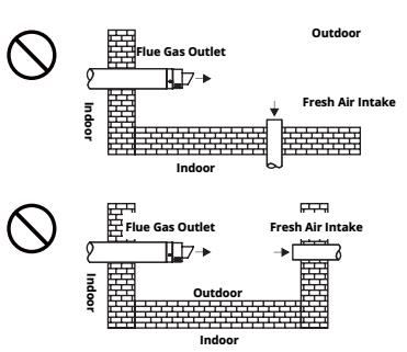
The following situations do not allow installation.
- The distance between the exhaust port and the new air outlet must ensure that the discharged smoke does not enter the room, and the position of the exhaust port and the new air outlet should be as far away as possible.
- The distance between the exhaust port and the fresh air outlet also needs to meet the positional relationship between households and buildings.
- During installation, it is necessary to check the position of the new air outlet around the exhaust port.
Condensation working principle and condensate discharge
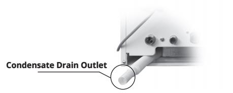
- Condensation working principle: By recovering the latent heat of flue gas generated during combustion, the heat released when water vapor condenses and is discharged in liquid form is harnessed to enhance efficiency. The condensate water produced during the condensation of water vapor is discharged through a dedicated collector.
- Do not arbitrarily change or block the condensate outlet.
- When connecting, please ensure there is no water leakage.
- The condensate water drainage pipe should be kept naturally downward and should not be folded upward.
Attention! Since this product lacks a condensate neutralization treatment device, the condensate can only be discharged into non-metallic sewage pipes. Condensate water that has not been diluted or neutralized should not be directly discharged into pipes other than domestic sewage drainage pipes or onto the surface.
Connection of control device
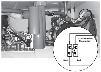
- This product can be equipped with an indoor temperature controller, which is used to control and display the temperature of the heating room.
- Loosen the terminal screw that connects the short-circuit wire and remove the short-circuit wire;
- Connect the two wires of the room temperature controller to the terminal blocks respectively.
Warning! The two wires inputting into the controller can only carry switch signals, and must not have any external voltage or current signals; otherwise, the controller may be damaged.
Water pressure characteristic curve
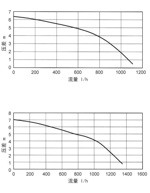
Important Notice:
This document is intended for reference by qualified installation and service personnel only.
Other individuals may read the contents for information purposes, but must not carry out installation, adjustment, disassembly, or any operation on the equipment.
Unauthorized operation by unqualified personnel may result in safety risks, and the safety of such operations cannot be ensured.